|
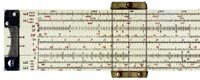
Engineering calculations
before the transistor.
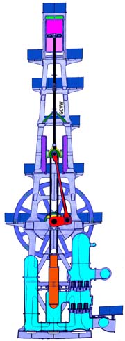
Side View
R.D. Wood
Triple Expansion
Crank & Flywheel
Water Pumping
Steam Engine
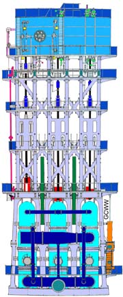
Front View
^Top^
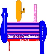
Surface Condenser
R.D. Wood Engines
^Top^
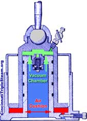
Dual Chamber Vacuum
Dashpot
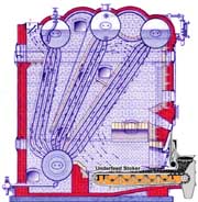
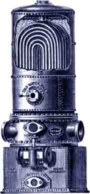
Stirling 4-drum
Water-Tube Boiler
with
American Underfeed Stoker
3-Steam Drums,
1-Mud Drum
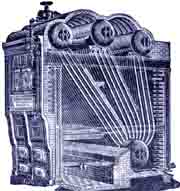
Stirling 4-Drum
Water-Tube Boiler
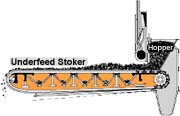
American Underfeed Stoker
^Top^
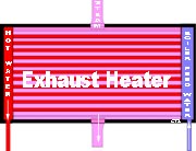
Exhaust Heater
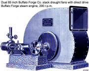
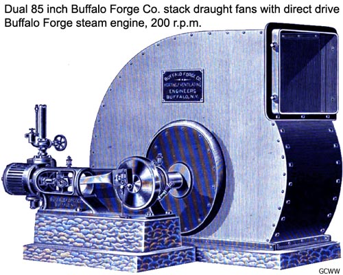
85 inch Buffalo Forge stack draught fan with direct drive Buffalo
Forge engine
Berryman Feed Water Heater
and grease separator
for support engines
Wheeler Surface Condenser fitted with a
Mullan Valveless Air Pump
for the support engines
^Top^
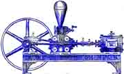
H.R. Worthington
Feed Water Pump
for support engines
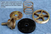
Click to expand
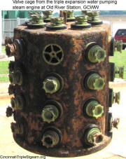

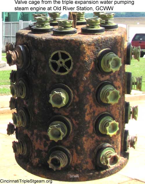
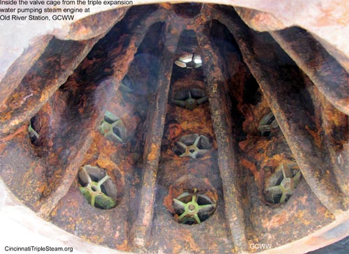
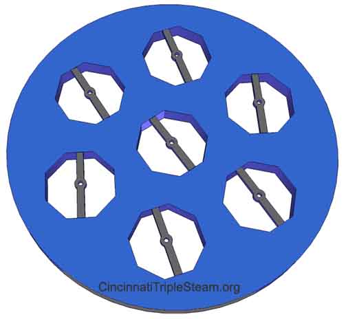
One of 7 Poppet Valve Cages
40 Valves/Cage
in each of two
assemblies
for each
of three pumps
^Top^
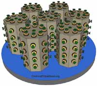
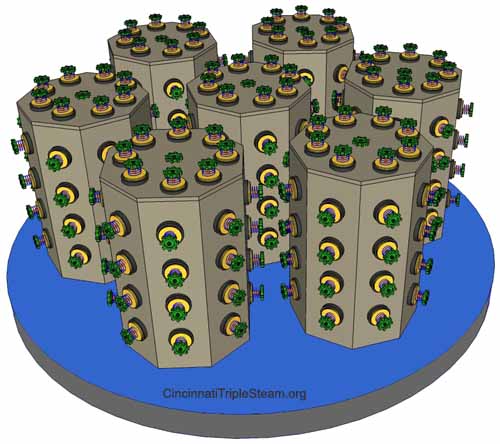
Pump Poppet Valve Assembly
7 cages @ 40 valves/cage
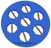
Pump Valve Assembly Base
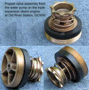
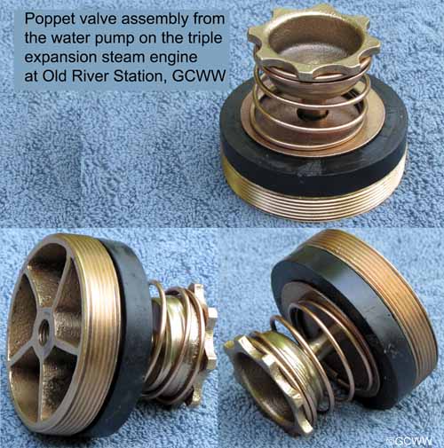
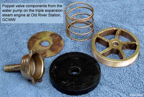
Water Pump Poppet Valve
 |
|
Building Design |
Cincinnati Architect, Gustave W.
Drach |
|
Engine Design |
John H. Lewis - R. D. Wood & Company
400 Chestnut St.- Philadelphia, PA |
|
Engine Manufacture |
Camden Iron Works, Camden, New Jersey |
| Engine Type |
Vertical triple
expansion crank & flywheel |
| Bids from |
Lane & Bodley Company of Cincinnati, Ohio originally won the
contract to supply the engines. After two yeas of
non-performance and an unfavorable decision by the Ohio
Supreme Court, their contract was canceled and the re-bid
was among the following: Camden Iron Works,
Camden, NJ
Holly Mfg., Lockport, NY
E. P. Allis Co. Milwaukee, WI
Kilby Mfg. Co. Cleveland, OH |
|
Cost |
Engines, Boilers & Overhead Crane, $1,331,000 |
| Service |
October 29, 1906 to
May, 1963 |
| High pressure cylinder |
29
inches diameter. 150 p.s.i.g. |
|
First receiver |
27 p.s.i.g. |
| Intermediate pressure cylinder |
54
inches diameter |
|
Second receiver |
-2 p.s.i.g. |
| Low
pressure cylinder |
82
inches diameter, 22 inch exhaust port |
| Re-heaters |
2 |
|
Surface area of re-heater |
1st =122 ft2
and 2nd
=276 ft2 |
| Stroke |
96 inch |
| Steam pressure |
150 p.s.i.g. |
| Efficiency |
21.6% coal to
water. See
Coal to Water Efficiency |
| Steam valve
gearing |
Corliss with dual chamber vacuum dashpot for the HP
cylinder and the inlet to the IP cylinder.
Balanced Poppet on the exhaust for the IP cylinder
and for both the inlet and exhaust on the LP cylinder (inlet
spring loaded, exhaust weight loaded) |
| R.P.M. |
15.5 (range 11 to
15.5) |
| Piston speed |
248
feet/minute or 2.82 m.p.h. |
| Horse power |
1,000 |
| Flywheel |
2 x 24
feet diameter, 40 ton, assembled in sections and secured
with dog bone locking keys. |
| Starting/Stopping |
The traditional Barring engine (also called a Jacking engine
or Kicking engine) was not used to start this engine.
Instead, the engine was rolled using the procedure listed
below. (nominal process steam was 150 p.s.i.g.)
Start engine procedure:*
- Preheat engine setting jacket steam and re-heater
steam to 65 p.s.i.g.
- Begin oil drips 10-15 minutes prior to starting.
- Open engine drains to bypass steam traps.
- Adjust air pressure in both the suction and the
discharge force chambers.
- Load the water pumps using the bypass source
until about 65 p.s.i.g.
- Open the main water inlet valve prior to opening main
discharge valve. Later on cone valves replaced the gate
valves and required verification of 200 p.s.i.g. water
pressure
for cone valve operation.
- Set governor to lowest speed
Roll engine by:
- Charging the first receiver to 30 p.s.i.g. steam.
- Slowly apply process steam to the HP cylinder until
about -7 p.s.i.g. is achieved in the condenser and throttle
back until the condenser achieves -13
p.s.i.g., and the governor has kicked in.
- If the HP piston is at dead center for crank-end or
head-end, the overhead crane is used to nudge the
flywheel off dead center.
- Close bypass to first receiver and adjust to about
22-24 p.s.i.g.
- Close drains and check for about -5 p.s.i.g. in the
second receiver.
- Slowly bring engine to operating speed.
- Check dashpots and valves for proper operation
- In case of trouble or emergency, knock out the vacuum breaker and
the engine will immediately stop.
Stopping the engine in normal operating conditions required skill and practice to
prevent the HP cylinder from ending at TDC.
* Starting procedure from
Stationary Engineer Jim Hoctor Sr. operating notes and input
from Paul Kraus. |
|
Bearing Gland Packing |
Initially oakum impregnated with paraffin and later on
asbestos impregnated with graphite |
|
Length of eccentric
shaft |
30 feet |
| Length of main
shaft |
10 foot 2
inches |
| Diameter of main
shaft |
19
inches |
| Length of main
shaft journals |
28
inches |
| Diameter of main
shaft journals |
19
inches |
| Length of crank
pin journal |
10
inches |
| Diameter of crank
pin journal |
High pressure and low pressure journal, 10 inches.
Intermediate pressure journal, 14 inches |
| Length of cross
head pin journal |
10
inches |
| Diameter cross
head pin journal |
10
inches |
| Weight |
1,400 ton |
| Height |
104
feet |
|
Base, cast iron |
23 foot 7 inch deep X 36 foot 4 inch wide x
28 inch tall |
|
Working decks |
11
decks accessed by stairs and elevator. The cast iron valve
decks were replaced with cast steel decks in 1915 |
|
Ancillary
Equipment
Attached |
A surface condenser,
wet air pump, boiler feed pump, air compressor, bilge pump,
and exhaust
heater |
| Condenser |
The attached surface condenser is
located in line with the 48 inch discharge header with the entire
water discharge passing
through it.
In addition, two Wheeler surface condensers each equipped
with a Mullan air pump were in the boiler room to handle the
exhaust steam from the ancillary engines |
| Condenser size |
62 inch diameter x 12 feet, 4 3/4
inches
long |
|
Condenser pressure |
-13.8 p.s.i.g.
nominal |
| Condensing surface |
2,130 ft2 |
|
Air compressor, attached |
3 3/8 inch plunger X 96 inch stroke |
|
Bilge pump, attached |
3 inch plunger X 96 inch stroke |
|
Boiler feed water pump, attached |
2 3/4 inch plunger X 96 inch stroke |
|
Wet air pump, attached |
28 inch diameter X 30 inch stroke |
| |
|
| Heating surface of
exhaust heater |
150 sq. ft. |
|
Ancillary Equipment Detached |
|
|
Boiler feed water pumps |
2- Henry R.
Worthington 10" x 6" x10" |
|
Boiler feed water pump for auxiliary equipment |
1- Berryman |
| Detached air
compressor |
by Westinghouse |
|
Pumps |
|
| Pumps/engine |
3 |
| Pump type |
Plunger,
a nickel iron plungers replaced all the cast iron plungers in
1932. |
|
Pump plunger |
Diameter =
3 1/8 feet or 37.5 inches, Length = 14 feet
24 Tons |
| Diameter of pump
barrel |
54 inch outside
packed |
| Diameter of pump
valve force chamber |
74 inches |
| Pumping
capacity/engine GPD *** |
Rated at 30,000,000 rated; Tested at 30, 878,124 |
| Gallons/Revolution |
Rated at 1,361.7, tested at 1,377 |
| Tons
of water moved / Revolution |
11.46 tons/engine, 45.84 tons/station/revolution |
| Stroke |
96
inches |
| Inlet nozzle |
48 inch to engine header, 40 inch to pump |
| Outlet nozzle |
40 inch to header,
48 inch to dual
60 inch outlets |
| Discharge pressure |
60
p.s.i.g. nominal |
| Effective area of
pump valves/pump |
1,665 sq in which is 51% above plunger area |
| Suction
poppet valves/pump |
280 at 3.5 inch OD, 7 cages, 40 valves/cage |
| Discharge
poppet valves/pump |
280 at 3.5 inch OD, 7 cages, 40 valves/cage |
|
Boilers |
|
| Boilers |
9-Stirling water tube boilers, eight at 424 HP and one at
529 HP, plant h.p. = 4,500 in 1921.
New boilers in 1920 and 1921
In 1906 the Stirling Company, with works in Barberton, Ohio, merged with Babcock and Wilcox
of New York. |
| Coal feed |
American underfeed
stokers, later on, Forced draught Riley
Stokers |
| Boiler tubes |
176 tubes, 3
inch diameter |
| Steam drums |
3 at diameter
of 36
inch , length 10 feet 9 inches |
| Mud drum |
42 inch X 9 feet 3 inches. |
| Steam pressure |
150
p.s.i.g. |
| Seam piping |
Fourteen inch pipe
delivers steam to the engine room arranged to use either
saturated or super-heated steam and branches into two lines
with two engines taking steam from each branch.
Exhaust steam from the LP cylinder flows through the
exhaust heater into the condenser. The air pump removed air,
oxygen, CO2 and uncondensed steam from the condensate chamber while
maintaining a near perfect vacuum (-13.8 psig) in the chamber. |
| Steam moisture |
2.2% at engine, 2%
at boiler |
| Heat boosters |
Green Economizer: Steel tube boiler feed-water heater
Foster super-heater: is a drawn
steel tube with cast iron radial fins heat shrunk onto the
tubing and allows better heat transfer from boiler gases to
steam than tubing without fins. The foster
Super-heater added 100°F to the steam
temperature and contributed another 200 HP
Auxiliary Hearer: exhaust steam from the ancillary engines
flowed through a Berryman type boiler feed water heater
and grease separator prior to entering the Green Economizer. |
| Gases leaving
boiler |
437°F |
|
Gases leaving super heater |
373°F |
|
Stack temperature |
196°F |
| Water evaporated
per 1 lb. dry coal |
10.687 lb., boiler
contribution 95%, economizer contribution 5% |
|
Condensate from the R. D. Wood Engines |
Boiler feed water
originated in the hot well for the surface condenser and was
collected in dual condensate storage tanks where the boiler
feed pump attached to the main engine takes suction.
From there water was forced by the attached feed pump
through the exhaust heater, through the deaerating plant,
through the auxiliary heater and through the Green
economizer into the boiler. Water from the softening and
deaerating plant was 92°F, increased to 142°F from
the exhaust heater and left the
economizer at 200°F.
Deaerating plant installed in 1922 |
|
Feed water from auxiliary engines |
Two 10 inch x 6 inch x 10 inch H. R. Worthington boiler feed
pumps. |
| Work duty coal |
Rated at 115,000,000 ft lb. of work for every 100
lb. of coal (Tested at 152,875,648 ft lb.)
See
Coal to Water Efficiency |
| Work duty steam |
172,925,997 ft lb. per
1,000 lb. of dry steam, weir measurement |
| Boiler House |
60 foot
X 180 foot,
Oolitic* dimensioned Bedford limestone, exterior rock faced, and inside sawed
smooth and rubbed. Boiler room floor of concrete, toilet
room red American tile, office and store room was matched yellow
pine flooring. Steel roof and lantern frame covered with
vitrified** "S" tile. Individual lockers for all employee,
toilet rooms with shower baths and other conveniences.
*Oolitic dimensioned limestone = grain size .25-2mm
**Vitrified Tile is a tile is created by the Vitrification
manufacturing process which has very low porosity and water
absorption, making it stain-resistant and strong. |
| Smokestack |
8 foot ID, 175 foot high of brick on circular stone base resting on a
concrete foundation with a diameter of 35 foot and 8 foot deep. The
stack is faced with light buff-colored radial Kittanning
pressed brick and topped with a cast-iron cap. Forced
draught
was provided by two 8 inch by 10 inch Buffalo Forge
Co. engines each direct driving an 85 inch Buffalo Forge Co.
fan , nominal R.P.M., 200. |
| Coal |
|
| Coal storage |
An elevated steel building supported by
steel columns, 69 foot X 225 foot kept the coal dry during
periods of high water and provided sufficient coal storage
for periods of low river level. 7,980 tons
were stored in 114 elevated pocket
hoppers each holding 70 tons, and equipped with a coal spout
valve leaving 6 1/2 feet of head room above the narrow
gauge tracks running lengthwise underneath the pocket hoppers. |
| Coal
usage |
26 tons (average daily) |
| Coal
supply |
Coal was originally received by barge and
occasionally by truck in the later days. A railroad siding
had been extended to the coal bunkers to provide for rail
delivery, but never use for that purpose. |
| Coal delivery |
Coal was elevated from river barges via a
dual narrow gauge rail system installed from low river water
level to the top of the three story coal hoisting house
using a steam hoist cable pull for dual two ton
capacity steel dump cars (one traveled up while the other
returned to river's edge) and deposited onto a cross belt conveyor,
and distributed by means of shuttle
belt conveyors to the 114 pocket hoppers. |
| Boiler coal
delivery (Coal Passers) |
Coal was
switched to the boiler house from the coal storage building
using a narrow gauge
rail system with boiler charging cars powered by an electric
locomotive engine about the size
of a golf cart, called the "Dinky". Boiler ash cars were switched using the same
locomotive. Coal was dumped on the floor in front of each
boiler and shoveled into the stoker hopper using coal shovelers.
1924, an overhead rail suspended hopper
system called the "Lorry" delivered coal to each stoker
hopper and was supplied by a coal hoist in a new three story
poured concrete lifting house at the front of the boiler
house. |
| Coal size |
Pittsburg Nut &
Slack which is 1 1/2 inch and 3/4 inch respectively provided 13,000
BTU
per pound of coal. |
|
Coal tests |
Moisture 2%, Ash from coal 8%, Slate in coal 1% |
| Pump Pit |
Built by F. H. Kirchner & Co., of
Cincinnati, the circular tapered, below grade wall, is 98 feet
inside diameter and 85 foot high, using circular sawed
Oolitic dimensioned
Bedford
Limestone* fifteen feet thick at the bottom and four
feet thick at the top with the inside face being plumb and
fine-pointed. The above grade masonry uses
a
Romanesque Revival architectural style with rock faced
Oolitic dimensioned Bedford limestone, and the inside lined with Tiffney white
enameled brick. Vitrified* "S" tile covers the conical roof |
| Steel Casing |
A masonry
embedded 1/4 inch
riveted and caulked steel cylinder extending from the pit
floor to 70 feet high assures a water tight pump pit. |
| Pit
floor |
85 feet below elevation, -5.5 feet below river bed |
| Foundation and
caisson |
128 feet
diameter by 12 feet thick solid 12" x 12"
air-dried white oak timber
crib foundation rest upon the 7 feet high tapered-edge
caisson cribbing using crisscrossed wood shoes with 21
excavation chambers. |
| Inlet stand pipe |
10 foot
diameter riveted steel setting on bedrock |
| Caisson ballast |
72 foot high
with an OD of 23
feet and an ID of
13 feet, cast iron, 4,200 ton, Individual sections weighing 6 ton each. |
| Station
Electrical Supply |
Three units,
each consisting of a DeLaval steam turbine driving two 75
KW, 4 pole Crocker Wheeler, 230 volt direct current
generators provided electricity to both river station
and the filtration/treatment plant. |
| Station
Elevator
and Stairs |
Warner Elevator Manufacturing Company
from Cincinnati, Ohio provided a 2,500 lb. capacity, 230 Vdc motor driven elevator
that traveled between the
engine operating floor level and the pump pit floor level. Two spiral stair cases extended from the pit floor to
the eccentric deck. A railed staircase extends from the
engine floor to the wheel deck. The railing for all stairs and elevated
walkways was bright work polished brass. |
| Overhead
Hoisting Crane |
From the Morgan Engineering Company,
Alliance Ohio, provided a 3 motor circular traveling radial
crane with a span of 49 feet 6 inches and a 30 ton lift of
110 feet. The electric motors use Morgan controllers with
adjustable speed and direction controls. All motors are 230 Vdc and included a
30 HP hoisting motor, a 25 HP a bridge
motor and a 5 HP trolley motor. The crane
was ordered on April 26, 1901 by the Camden Iron works
and shipped to the California, Ohio facility on November
18, 1903.
Design of the engine and its
pumps allowed every principal part to be
reached and removed by the overhead hoisting crane without
disturbing any other part of the machinery. |
| Operations |
Three engines
could be operated at rated capacity without increasing the
regular daily staffing of 36 employees. The Station
Chief was in charge of the entire operation while the
licensed stationary engineer was in charge of the engine
room and the licensed fireman was in charge of the boiler
house . Each eight
hour shift maintained a minimum staffing of one licensed stationary engineer, four oilers,
one licensed fireman, two coal-passers, and an assistant Chief
Engineer. Daily staffing include a clerk, one machinist and
helper, one boiler cleaner, one locomotive operator, a
janitor, and three or four grounds keepers.. |
|
Number of steam engines at River Station (21) |
4 - water pumping engines, R.D. Wood
4 - economizer engines
2 - stack draught engines, Buffalo Forge Co.
2 - boiler feed water engines for pumping condensate from
ancillary engines and ancillary equipment , Henry R.
Worthington
9 - stoker engines |
|
* * * GPD, Gallons Per day |
|